Inaccurate moisture measurement of silage at harvest can lead to excessive moisture transport, poor packing, excessive dry matter, quality loss and poor fermentation.

Moisture measurement of forage and other high-moisture feeds is critical at feeding time to properly balance nutrient concentrations.
Forage moisture can vary significantly over time and with location in a storage structure; therefore, rapid, accurate and inexpensive methods of evaluating moisture are needed.
Methods for on-farm analysis include electronic meters, microwave drying, Koster™ testers and drying ovens. Researchers evaluating alternative methods consistently use a drying oven as the standard.
Most agree that use of a microwave oven is an accurate method (typical error -2 to +1 percent), but it requires more time and operator skill than most alternatives.
As evidenced by the multitude of extension fact publications and Internet informational pages, microwave drying of small samples appears to be the on-farm method of choice; however, this method requires constant supervision and can lead to inaccurate results due to burning of a sample.
A Koster tester does not require constant supervision, but it requires a significant amount of drying time and is less accurate (typical error ±3 percent) than a microwave oven. Electronic meters can be consistent but require frequent calibration.
The vortex dryer can be built for approximately $40 and is as accurate as a drying oven. Most hay samples can be dried in 15 to 20 minutes; most silage samples will dry in 40 to 60 minutes, depending on crop characteristics.
Accuracy of a vortex dryer
Accuracy of the vortex dryer was determined by comparing results from 200-gram (7.06-ounce) subsamples of 12 different forages dried in a vortex dryer and a drying oven.
Four replicates of each sub-sample were dried using each method. The vortex dryer average error was -0.1 percent. Moisture estimates were within 1 percent of the actual value 95 percent of the time.
There was no statistical difference between the vortex estimates and the drying oven estimates. Just because the method is accurate, however, does not mean the estimate from a sample is accurate.
Proper sampling is critical – particularly when there is variability within a field, from field to field, from load to load, across a bunker face, etc.
The vortex device and the associated method allows for replicate sample drying in a relatively short period of time.
With approximately the same time, effort and cost, a person could dry three 200-gram forage samples in three vortex dryers rather than three 100-gram samples in a microwave oven – there would be no risk of burning the samples and the larger vortex dryer samples reduce sampling error.
Building a vortex dryer
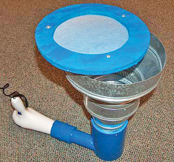
A completed vortex dryer is shown in Figure 1 (above right). The components required are listed in Table 1 (click here or on the image below to view table at full size in a new window); it takes approximately three hours to build the dryer once supplies are available.

It is important to use CPVC rather than PVC for the coupling and air entrance tube; blow dryers can heat the tube to a temperature which softens PVC.
With enough air flow resistance, the temperatures might also get high enough for PVC to release toxic fumes (above 140ºF). CPVC is rated for higher temperatures.
One critical aspect of the vortex dryer involves the placement of the air entrance tube so that air swirling occurs.
The air should enter the drying chamber tangent to the vertical chamber.
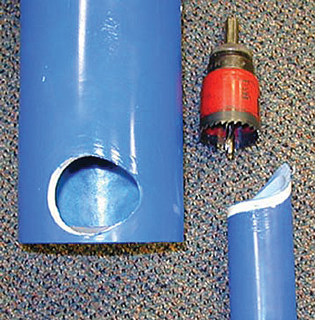
To properly place the air entrance tube hole approximately ¼-inch from the bottom, either use a hole saw or a large drill bit to drill a hole nearly large enough for the air entrance tube (Figure 2).
Use a rotary tool with a sander or a file to shape the hole so the entrance tube fits into the hole snugly.
The end of the entrance tube should be shaped to the contour of the inside of the drying chamber.
This can be done with a scroll, jig or band saw and a little filing or sanding.
Glue the air entrance tube to the drying chamber base using CPVC glue, since operating temperature may approach 140ºF.
The floor of the chamber should be inserted into the vertical chamber so the top of the floor will be flush with the bottom of the air entrance tube when it is installed (Figure 2). This eliminates a dead zone at the bottom of the drying chamber.
The dryer has a plastic sheet floor glued in place. Plywood could be used with screws installed from the outside to fasten the wood floor in place.
The base of the drying chamber can be made of PVC (less expensive) or CPVC. The metal duct fittings can be attached to each other and the CPVC or PVC base with either pop rivets or small bolts (put heads inside, nuts outside).
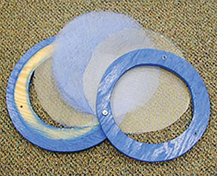
The vortex sample dryer lid is a sandwich of window screen, two layers of furnace filter, and window screen (Figure 3).
The lid frame illustrated was made of plywood and clamped together with small screws; the lid should be cut to fit snugly into the top of the chamber.
The lid eliminates sample loss during drying; it is important because as samples dry, particles will be flying around in the drying chamber.
Depending on the blow dryer used, the connection to the entrance tube may need to be changed.
A CPVC coupler will work in most cases with some sanding or filing to fit the blow dryer outside diameter.
It is recommended to glue the blow dryer to the coupler with glue for plastic which can tolerate the high temperatures (CPVC glue may work, depending on the plastic used to make the blow dryer); leave the coupler unglued from the air entrance tube. This will allow easy removal of the blow dryer from the vortex dryer, yet provide a rigid connection during operation. FG
—Excerpts from Penn State Extension Agricultural and Biological Engineering factsheet.
For more complete instructions on assembling a vortex dryer, (click here) to download the extension publication online.
PHOTOS
TOP: Figure 1. Assembled vortex dryer.
MIDDLE: Figure 2. Bottom of drying chamber and entrance tube ready for installation.
BOTTOM: Figure 3. Disassembled vortex dryer lid “sandwich” of window screen, furnace filter and window screen between two wooden rings. Photos courtesy of Dennis Buckmaster.